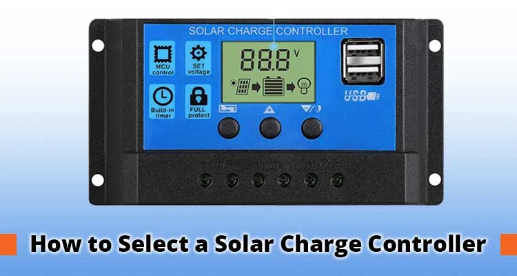
Nearly 40% of DIY off-grid solar failures originate from a mismatched or undersized charge controller — a component that costs less than 5% of a typical system budget. If you need to know how to choose a solar charge controller that fits your panel array, battery chemistry, and long-term expansion plans, this guide gives you the complete framework. The controller sits between your panels and your battery bank, regulating current and voltage to prevent overcharge, over-discharge, and thermal runaway. Browse the full solar and clean energy resource library for companion guides on every layer of a well-designed off-grid system.
Every component decision downstream — battery bank capacity, inverter sizing, fuse ratings, wire gauge — assumes the controller is correctly matched to the array. A wrong call here doesn't just reduce efficiency. It quietly degrades your battery bank over months and can create unsafe operating conditions before you notice anything is wrong.
This guide walks through controller types, sizing math, installation discipline, common failure modes, and a scaling strategy that keeps your system expandable from a weekend 200W build to a full 2kW off-grid array without replacing core infrastructure.
Contents
Your first decision shapes every other component choice. Two technologies dominate the market, and picking between them isn't purely a budget question. It's about array voltage, system scale, and where you're starting from.
PWM (Pulse Width Modulation) controllers regulate charging by rapidly switching the connection between panel and battery on and off. Simple, durable, and inexpensive — but they require the panel's nominal voltage to closely match the battery bank voltage, or you leave power on the table.
The trade-off is measurable. A 100W panel rated at 18V Vmp loses 20–30% of its capacity when connected through a PWM controller to a 12V battery. At small scale, acceptable. Across a 600W array, that loss funds an MPPT upgrade within a season.
MPPT (Maximum Power Point Tracking) controllers use DC-DC conversion to step higher panel voltages down to battery voltage, recovering energy that PWM discards. They continuously scan for the panel's peak power output and adapt in real time as temperature and irradiance shift.
For a detailed technical comparison covering efficiency curves, shading tolerance, and cost-per-watt analysis across system sizes, the dedicated breakdown of PWM vs MPPT solar charge controllers covers everything you need before committing to either technology.
Knowing the type is half the equation. The other half is matching the controller's ratings to your actual array and battery bank. Get the math wrong and you either clip your harvest or fry the controller on a clear summer afternoon.
Use the standard formula: divide total panel wattage by battery bank voltage, then add a 25% safety margin.
Example: 600W array ÷ 24V bank × 1.25 = 31.25A → select a 40A controller.
Never size to the edge. Panel output varies with temperature and irradiance spikes, and a controller running at 100% rated current continuously degrades faster than one operating at 75%. The 25% buffer isn't conservative padding — it's standard engineering margin for a DC system operating outdoors.
Before buying any MPPT controller, verify three voltage specifications against your panel string configuration:
| Panel Array (W) | System Voltage | Recommended Controller Amperage | Controller Type |
|---|---|---|---|
| Up to 200W | 12V | 20A | PWM or MPPT |
| 200–400W | 12V or 24V | 30–40A | MPPT recommended |
| 400–800W | 24V or 48V | 40–60A | MPPT required |
| 800W–1.5kW | 48V | 60–80A | MPPT required |
| 1.5kW+ | 48V | Multiple controllers or 100A+ | MPPT required |
Matching the controller to your battery chemistry is equally critical. If you're running lithium iron phosphate cells — like the Battle Born LiFePO4 deep cycle batteries that dominate serious off-grid builds — your controller must support manually adjustable charge profiles, not just fixed lead-acid factory presets.
Correct sizing gets you to the starting line. Correct installation keeps you there for a decade. Most premature controller failures trace back to avoidable wiring and mounting errors made during initial setup — problems that show up six months later with no obvious cause.
The Powermax PM4 converter review covers DC wiring discipline and fusing strategy in detail for RV-style DC systems — the same principles apply directly to any solar charge controller installation in mobile or semi-permanent setups.
Pro tip: Mount your controller in the same thermal environment as your battery bank — temperature compensation only works accurately when the sensor reads the battery's actual temperature, not the ambient air in a hot engine bay or exterior compartment.
Lead-acid batteries require charge voltage adjustment of approximately −4mV per cell per °C above 25°C. LiFePO4 chemistry is more tolerant but still benefits from accurate temperature data to optimize cell longevity. A controller mounted in a compartment swinging between 0°C and 50°C while the battery sits in a climate-controlled interior will consistently miscalculate charge termination voltages.
For authoritative standards on solar charge controller safety ratings and NEC compliance requirements for permanent installations, the U.S. Department of Energy's photovoltaics resource outlines UL listing requirements and electrical code considerations that apply to any grid-tied or off-grid system on a structure.
The most damaging solar charge controller mistakes don't trigger error codes. They run silently in the background, degrading your battery bank's cycle count and clipping daily harvest for months before you diagnose what's happening.
Charging a LiFePO4 battery bank on a sealed lead-acid preset is the fastest way to destroy a thousand-dollar investment. Most controllers ship defaulted to flooded lead-acid. Verify your battery profile before connecting the panel array for the first time — not after.
When in doubt, pull the battery manufacturer's datasheet and enter parameters manually rather than trusting a preset labeled "Lithium." Preset accuracy varies wildly across controller brands.
A controller fault that goes undiagnosed for two weeks can push a battery bank into sustained over-discharge or chronic overcharge. Catching the warning signs early is the difference between a firmware reset and a full battery bank replacement.
Quality MPPT controllers use LED blink codes or LCD fault codes to communicate status. Know what these mean before you need them:
Start diagnostics with basic electrical measurements before assuming the controller is faulty. A quality outlet tester and multimeter kit lets you verify panel open-circuit voltage, battery terminal voltage under load, and controller output voltage independently — ruling out the panel and battery before condemning the controller.
The best solar systems are designed to grow. The worst require a complete teardown the moment you want to add 200W of panels. The difference comes down to decisions you make before you buy your first component — not after the conduit is buried in a wall.
The discipline of building expandability into a system from the design phase — not retrofitting it later — is demonstrated clearly in the UNLV zero-energy Native American home design project, where solar architecture decisions made at the planning stage eliminated the need for expensive infrastructure changes down the line.
A controller without monitoring is a system you're flying blind. Modern MPPT controllers offer Bluetooth or Wi-Fi connectivity, and the data they surface is actionable in ways that pay for the feature within the first season.
Even a basic controller with an LCD display beats a black box. Invest in visibility early. It pays for itself the first time it catches a panel underperforming at 60% output due to a corroded MC4 connector.
No. A charge controller is designed to regulate power delivery to a battery bank. Running one without a battery connected causes unregulated voltage spikes that can destroy the controller's internal circuitry and any DC loads attached to it. Always connect the battery first, then the panel array — in that order, every time.
Exceeding the wattage rating causes thermal throttling, output clipping, and accelerated internal component degradation. In MPPT units, sustained overload can permanently damage the DC-DC conversion stage. The controller caps output at its rated maximum, so you lose harvest from the excess panel capacity and risk a shortened controller lifespan — both losses at once.
System voltage is driven by battery bank configuration and the loads you're running. For arrays under 400W powering 12V appliances directly, a 12V bank is practical. Above 400W or when running a substantial inverter, 24V or 48V reduces wire losses significantly and enables more efficient power delivery. Most serious off-grid builds default to 48V for scalability and reduced conductor sizing costs.
For a system under 200W using panels whose Vmp closely matches your battery voltage, a PWM controller is genuinely adequate. Once your array exceeds 200–300W, or you're connecting modern high-voltage panels (20V+ Vmp) to a 12V bank, an MPPT controller recovers its cost premium through improved harvest efficiency within one to two seasons — and it gives you a platform to expand without replacing the controller.


About Malcolm Woods
Malcolm Woods is a technology writer and sustainability advocate with a background in consumer electronics and a long-standing interest in the intersection of technology and environmental impact. He has spent years evaluating tech products — from smartphones and smart home devices to solar-powered accessories — with a focus on real-world performance, longevity, and value. At the site, he covers tech accessory reviews, smart home gear, buying guides, and practical how-to content for everyday technology users.
Go for the FREE Gifts. Or check out for free energy books from our best collection.
Remove Ad block to reveal all the secrets. Once done, hit a button below